YouTube
http://www.youtube.com/watch?v=ox1DKE2OyWc
http://www.youtube.com/watch?v=TRWh1xNlrYI
http://www.youtube.com/watch?v=4BxvhrhfVng
Saturday, February 13, 2010
Sunday, January 31, 2010
part 4
General
The programer can control other aspects of the program so different hardware boards can be connected to it with different sampling and broadcasting time only by changing #defines.
Below are a few of the additional features

General
The programer can control other aspects of the program so different hardware boards can be connected to it with different sampling and broadcasting time only by changing #defines.
Below are a few of the additional features
- Telemetry – sending or receiving using XBee or USB.
- Sampling time – sampling time including time rate of each task.
- ADC bit size – sampling at 8 or 10 bits (reduce buffer size and transmission time).
- Buffer ADC size – number of ADC values in buffer which also control period of full buffer transmission.
- Buffer message size – size of max available space for messages in buffer.
- Number of channels to sample – from 1-8 sampling channels.
- Power saving – enable/disable leds, enable/disable buzzer, entering sleep mode in idle task.
- Usart debug modes – usart debug of telemetry messages, tasks duration, errors, parameters changing. Initialized procedure is seen in figure 8.
- Other debug - simulated input signals (sin,cos,etc), display tasks switch, see figure 9.

Figure 8: usart initialization plot
part 3
Algorithm
The code runs under freeRTOS environment (http://www.freertos.org/ ) and contains three major tasks, see Figure 5.

Algorithm
The code runs under freeRTOS environment (http://www.freertos.org/ ) and contains three major tasks, see Figure 5.

Figure 5: block diagram
part 2
Analog board
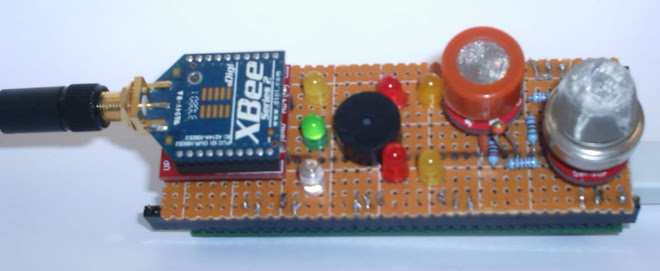
The analog board is used both for the sensors and for the XBee socket, see figure 3.
both gas detectors Methane CNG gas sensor – MQ-4 (http://www.sparkfun.com/commerce/product_info.php?products_id=9404 )
and Carbon Monoxide sensor – MQ7 (http://www.sparkfun.com/commerce/product_info.php?products_id=9403 ) need continuously 5V to operate in their working temperature (heating),so the board is always connected to 5V power source. This is also why the board is used in router configuration and can not be used as end device.
There is also a temperature sensor Thermistor 10k connected and used to measure temperature changes. (http://www.sparkfun.com/commerce/product_info.php?products_id=250 )

Analog board
The analog board is used both for the sensors and for the XBee socket, see figure 3.
both gas detectors Methane CNG gas sensor – MQ-4 (http://www.sparkfun.com/commerce/product_info.php?products_id=9404 )
and Carbon Monoxide sensor – MQ7 (http://www.sparkfun.com/commerce/product_info.php?products_id=9403 ) need continuously 5V to operate in their working temperature (heating),so the board is always connected to 5V power source. This is also why the board is used in router configuration and can not be used as end device.
There is also a temperature sensor Thermistor 10k connected and used to measure temperature changes. (http://www.sparkfun.com/commerce/product_info.php?products_id=250 )

Figure 3: analog board description
part 1
Project description
Figure 1 shows the Zigbee gas detector boards, the left board holds the analog part with an XBee module connector while the right board is the digital board with avr32 module AL-UC3AEB MCU, oscillator and regulators, this board was bought from http://alvidi.de/avr32_module.html

Project description
Figure 1 shows the Zigbee gas detector boards, the left board holds the analog part with an XBee module connector while the right board is the digital board with avr32 module AL-UC3AEB MCU, oscillator and regulators, this board was bought from http://alvidi.de/avr32_module.html

Figure 1: to the left analog board with XBee socket,to the right digital board with avr32 MCU
About this blog
my beliefs is that by sharing this with you and from reading your response will only help me to be beater in what I like to do
About this project
Hi
this is my first step in being able to create and build my own projects.
started with connecting an XBee to ATMEL MCU and after some weeks thinking what I can do with it I found small nice gas detectors.
then this project started.
I asked a day off each week for this and got three month to do it.
so this project took me 12 days.
it involve and freeRTOS running over AVR32, monitoring ADC gas sensors, buffering data and transmitting it over XBee
Subscribe to:
Posts (Atom)